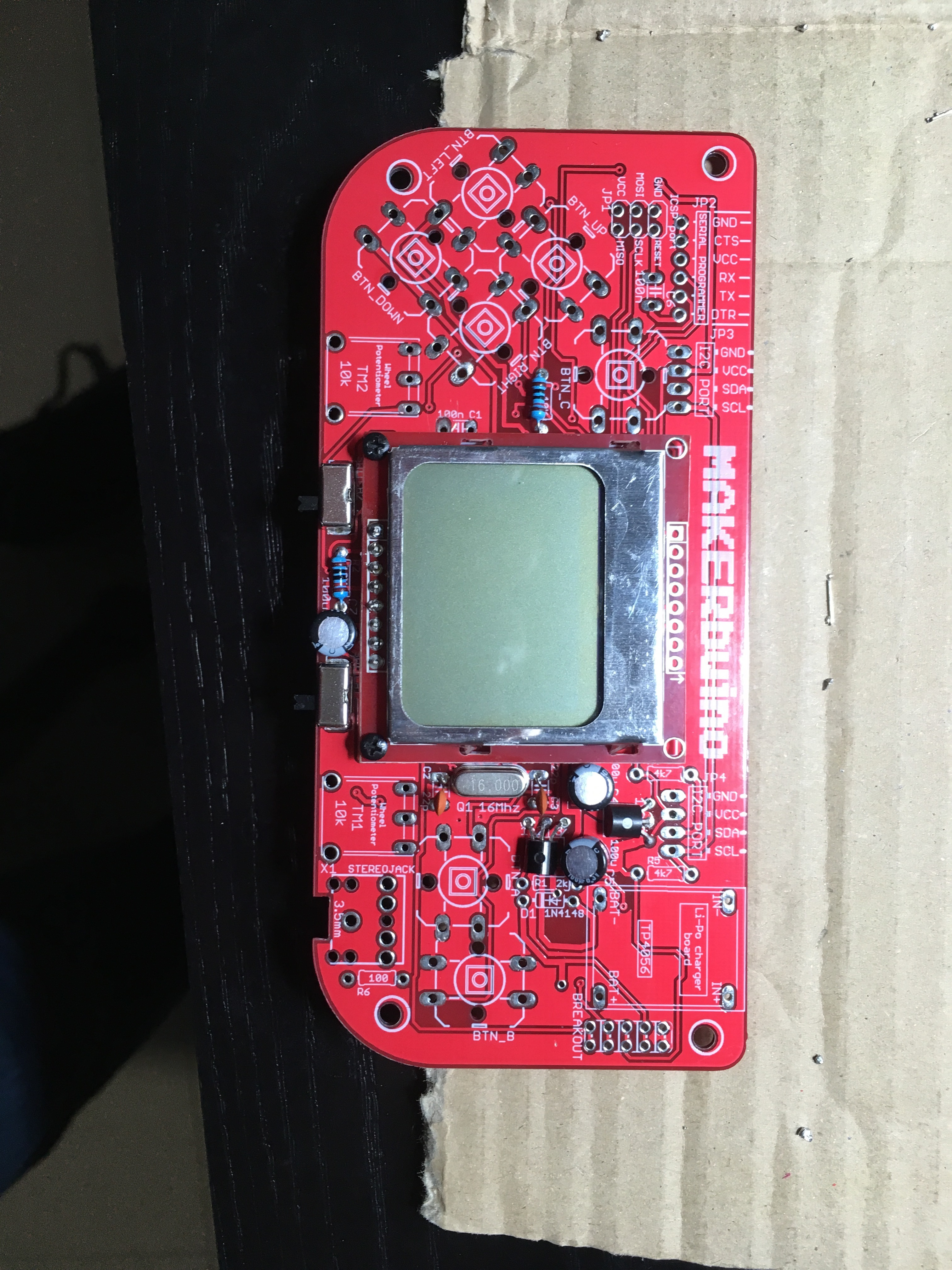
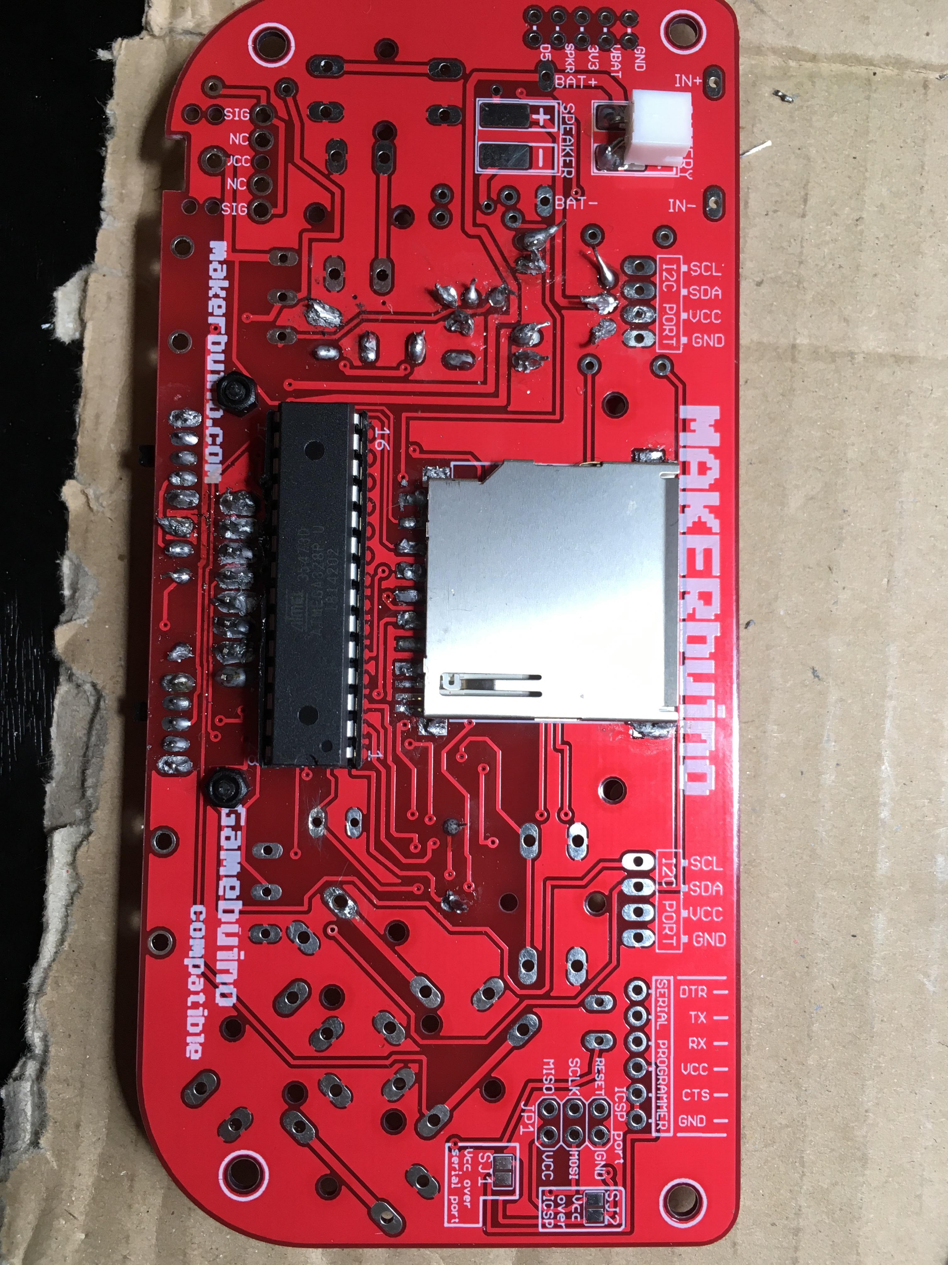
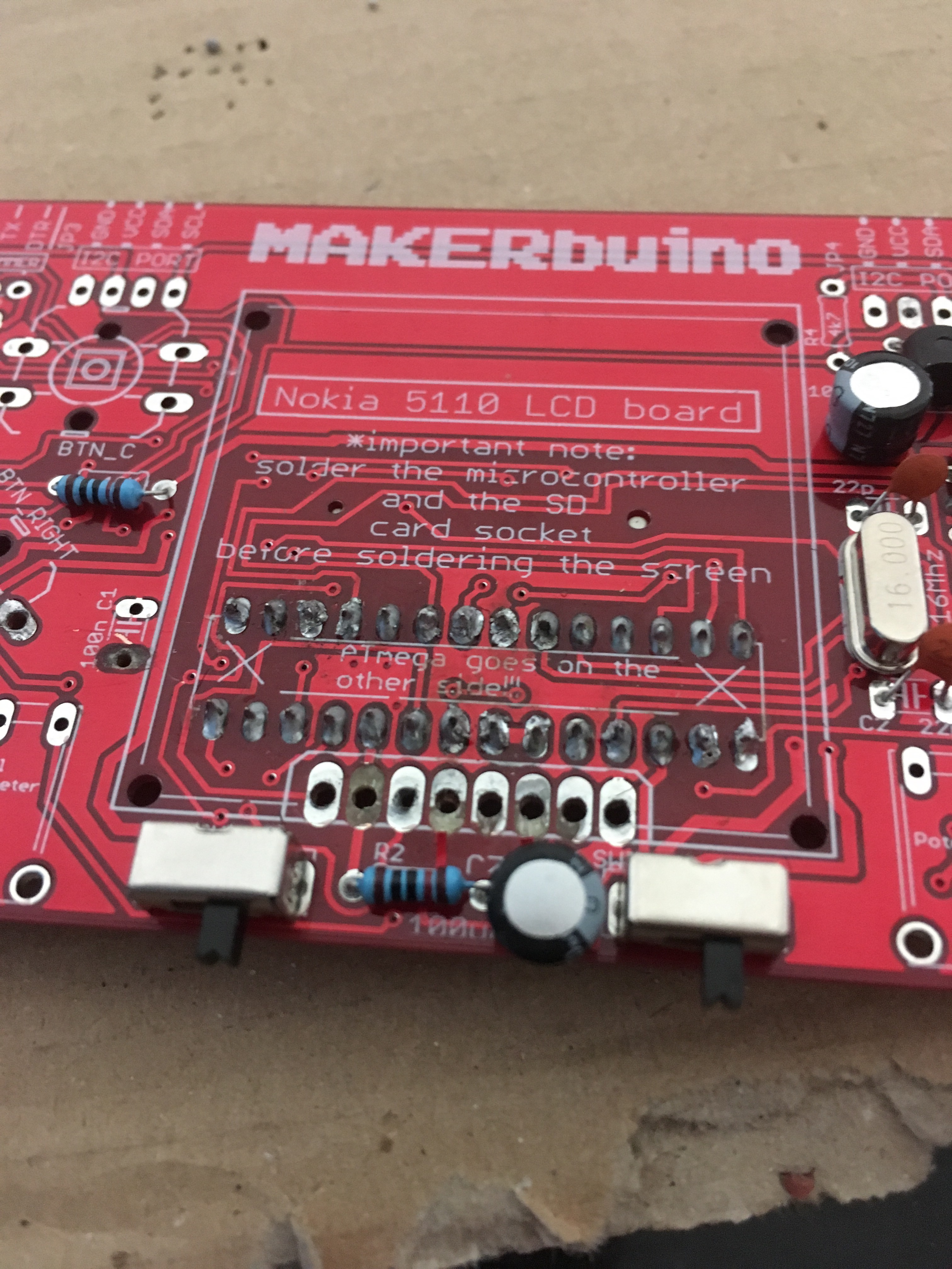
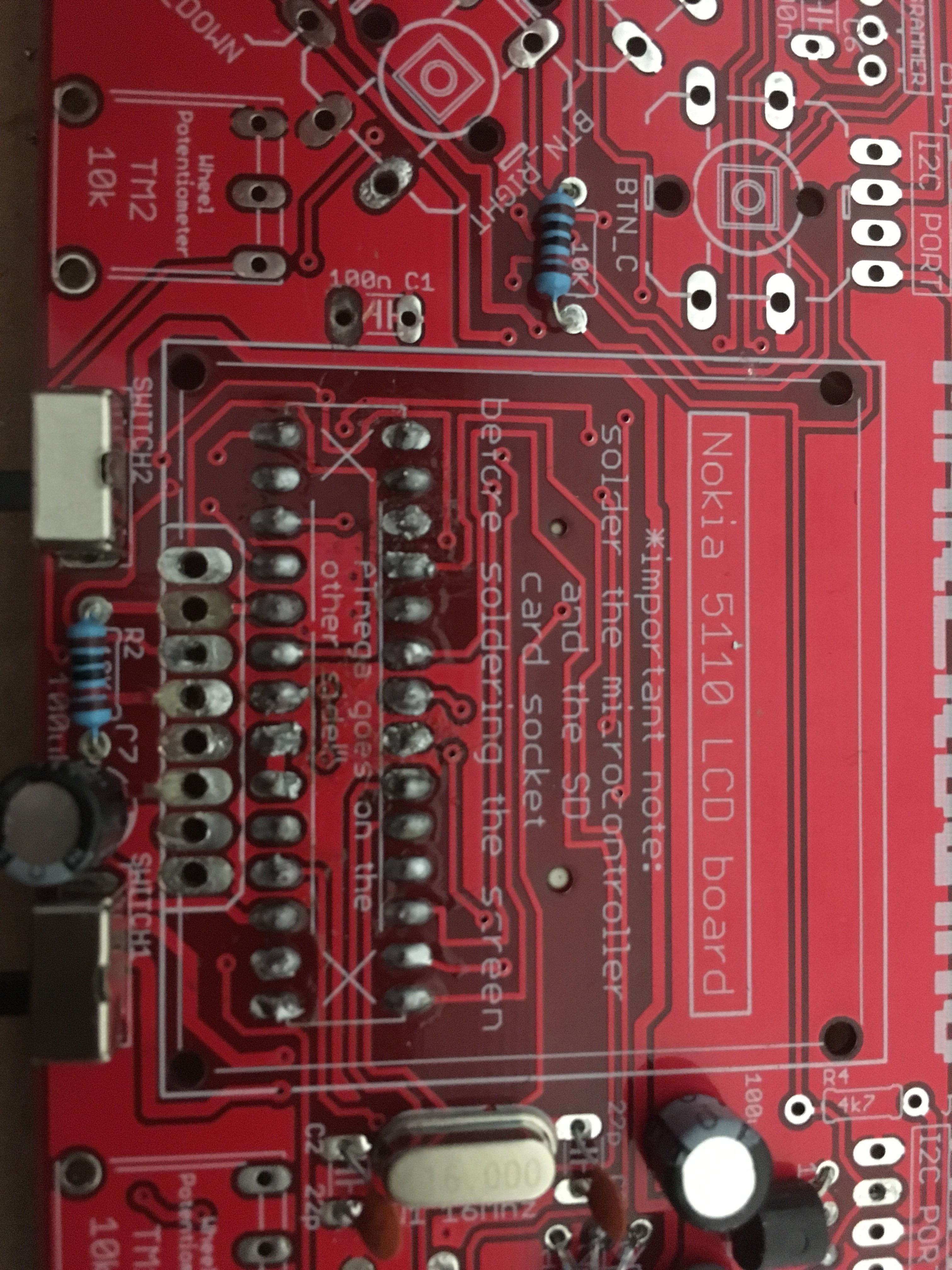
Tried to put together the kit but it seems I made some mistakes. Here are the pictures, front and back:
[I can’t put all the pictures here, being a new user, I’ll put them in the next post]
I tried looking into some other posts and I often read the tip of doing Step 13. So I tried that too, but still no results.
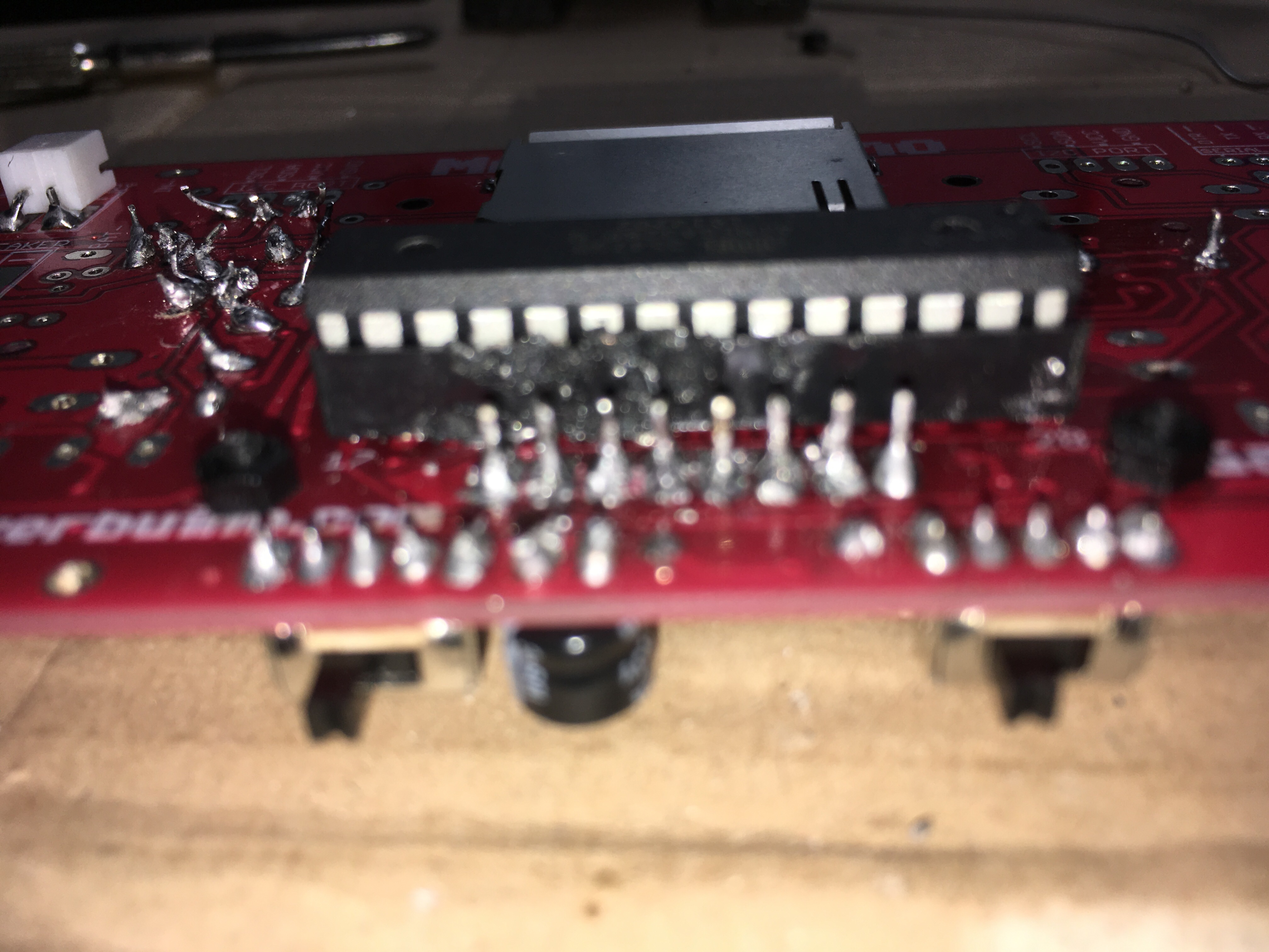
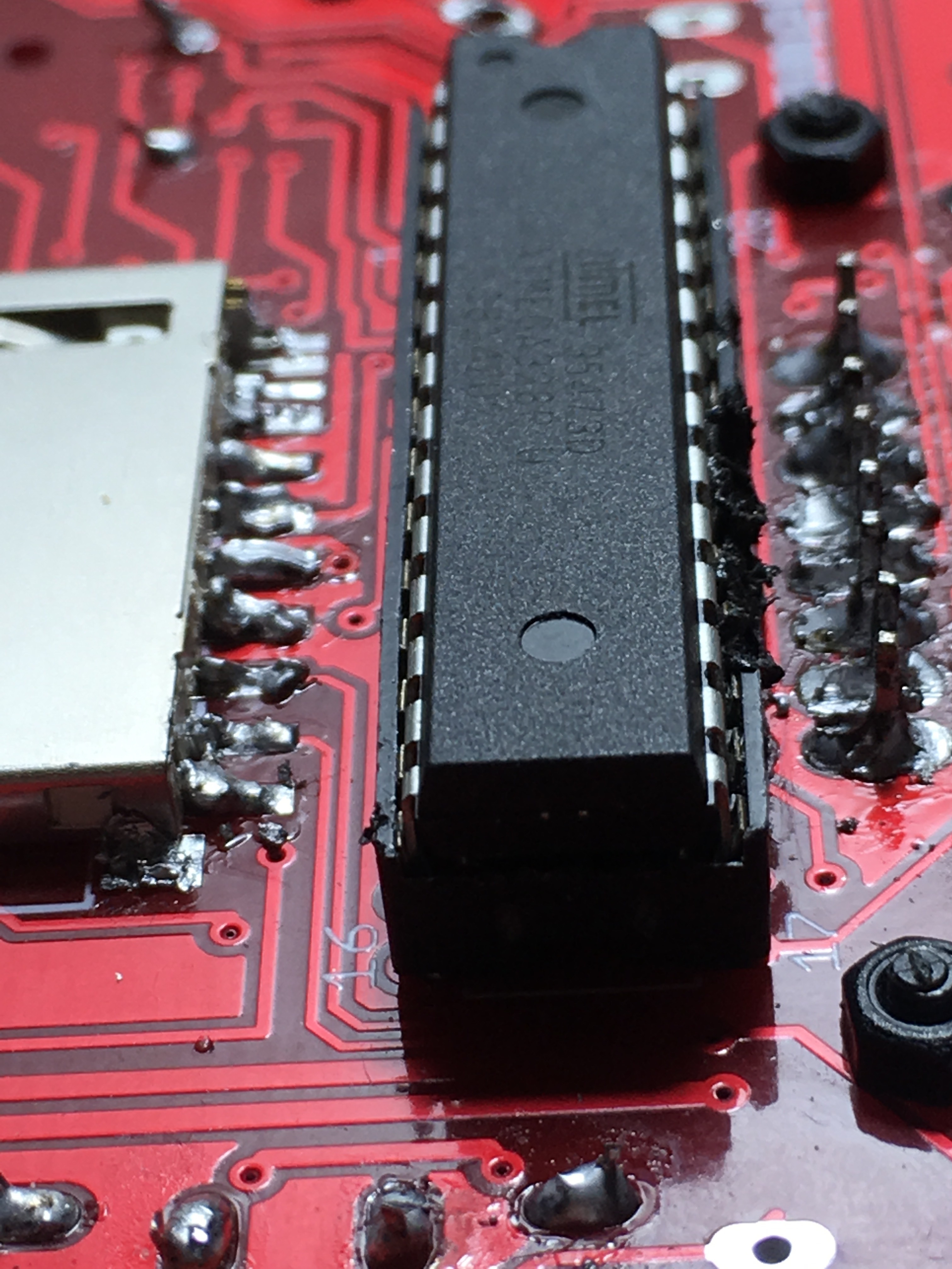
Also, I’m quite a newb and this is my first time soldering. Stuff got pretty messy while I was soldering the screen and this happened to the micro controller socket:
It took a while, but in the end I was able to put the micro controller in. Maybe I have not put it in the right way though, so here’s another picture.
I have a multimeter, so if it can help I could take some reading, if you explained me where I should put the probe.
Thanks for the help.
Update:
I removed the micro controller from the socket and following this post: Testing Point - Won't turn on
I checked the connections with my multimeter. Had appropriate readings on every of them. The micro controller however had a bent pin when I removed it, so I assumed I didn’t put it properly. Put it back in and tested again to see if the screen turned on and nothing.
At this point, what could the problem be?
Thank you again guys and sorry for being bothering you in the holidays period.
Hey,
Thank you for supporting MAKERbuino and I am sorry for the problems that you’re experiencing.
Please, send us the console to our address:
CircuitMess,
Maksimilijana Vrhovca 11,
47000 Karlovac,
Croatia
We cannot help you remotely any further so I’ll personally fix your console and get it returned to you.
You only need to send us the circuit board in order to make the package as light as possible.
Thank you for your understanding.
Sincerely,
Albert
Is there really nothing I can do to attempt to fix it myself? I bought a Makerbuino because is a DIY kit and if someone else fixed my mistakes and completed the project for me it wouldn’t be the same, you know.
Let me know.
Hey,
I understand your concern.
The problem most likely lies beneath the screen on the microcontroller socket - you probably need to redo those soldering joints.
You’d need to desolder the screen in that case and that is a tough job, that’s why I told you to send the kit back to us.
I’ll just make your console pass the first functionality test and you’ll get to do the rest of the work, don’t worry 
Of course, if you wish to desolder your screen and tinker further, feel free to do that, I just don’t have anything else to suggest.
Sincerely,
Albert
Just to make sure that I know my options, why do you say that desoldering the screen is tricky and if I were to do it, how should I approach it?
Also, I really am a newb so sorry for the stupid question, but checking the pin of the socket with the multimeter, the voltage readings were fine, shouldn’t this mean that it is soldered correctly?
@figuringout, desoldering multiple pinned components is always tricky. I’d suggest you to connect all the screen’s pins with solder and heat them together whilst trying to pull out the screen.
It sounds tricky and there are some tutorials describing this here:
https://www.sparkfun.com/tutorials/339
The voltage levels show that everything is ok with the power supply circuit, but they do not indicate whether the pins on the microcontroller socket were soldered correctly.
1 Like
Okay, I got it, thank you for explaining.
Thank you for the tip too, I think I’ll attempt it in these days.
1 Like
In the end, I was able to desolder the screen, although pretty roughly.
Here’s a picture:
I have ruined the pcb, haven’t I?
These are the soldering joints of the socket instead, I haven’t touched them yet:
With everything in these conditions, can I still manage to do something or have I done some permanent damage?
I also noticed that I got the pad off in another point too (at another time, trying to fix another mistake), although there is no component there yet:
Where it should go C1.
I made quite a mess, guess I need more practice soldering.
I’ve read on the forum that I could use wire to make te connections with the point where the pad is off. Would this work in my case? Do I have to do it with the screen pins too?
Thank you for bearing with me and this mess .-.
Hey Cris,
Yeah, desoldering multiple-pinned components is really tricky as I said. The soldering joints on the microcontroller socket were most likely causing the problem, they need to be repaired.
Quite a lot of copper was destroyed in the desoldering process and I’d suggest us sending you a completely assembled circuit board that you’ll be able to put in your casing and hook it up to the battery.
Thank you for your patience and understanding
Thank you for the answer, how do I proceed then?
Please, send me your address via a private message and we’ll ship you the circuit board for free.
1 Like
I’m going to do it in a minute, I really wanted to thank you for your time and your support
1 Like
Message receved, we’ll send you the circuit board ASAP.
Cheers!
I received the package, awesome!
1 Like