Have you restartet your Arduino a couple of times? There’s a synchronization bug I think.
I would sometimes get a corrupted picture that would be fixed by resetting the arduino. I must have reset it dozens of times while testing, so I think it’s not a synchronization problem.
That is the synchronization bug I’ve meant. I thought your misaligned/cutoff image on the TV was caused by that. That’s why I asked if you’ve already reset the arduino a couple of times 
Then there’s another problem causing your error. How long is the cable between the MAKERbuino and the Arduino? And how long is the cable between the arduino and your TV?
When I was testing my TV-Adapter I used the MAKERbuino Multiplayercable and some jumper wires to connect the MAKERbuino to the arduino which was in fact too long to transmit the signal properly. Changed to a much shorter cable did the trick for me.
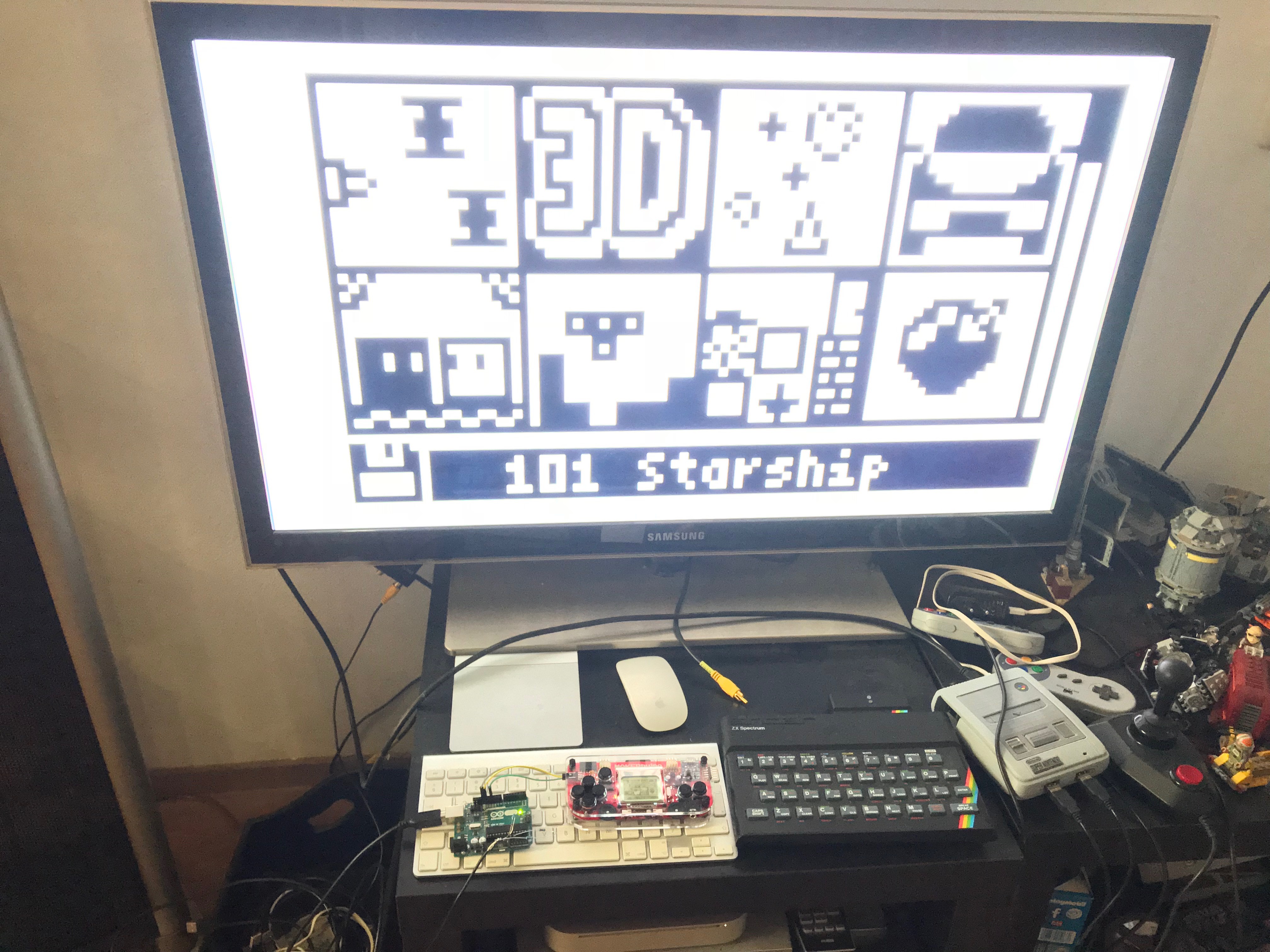
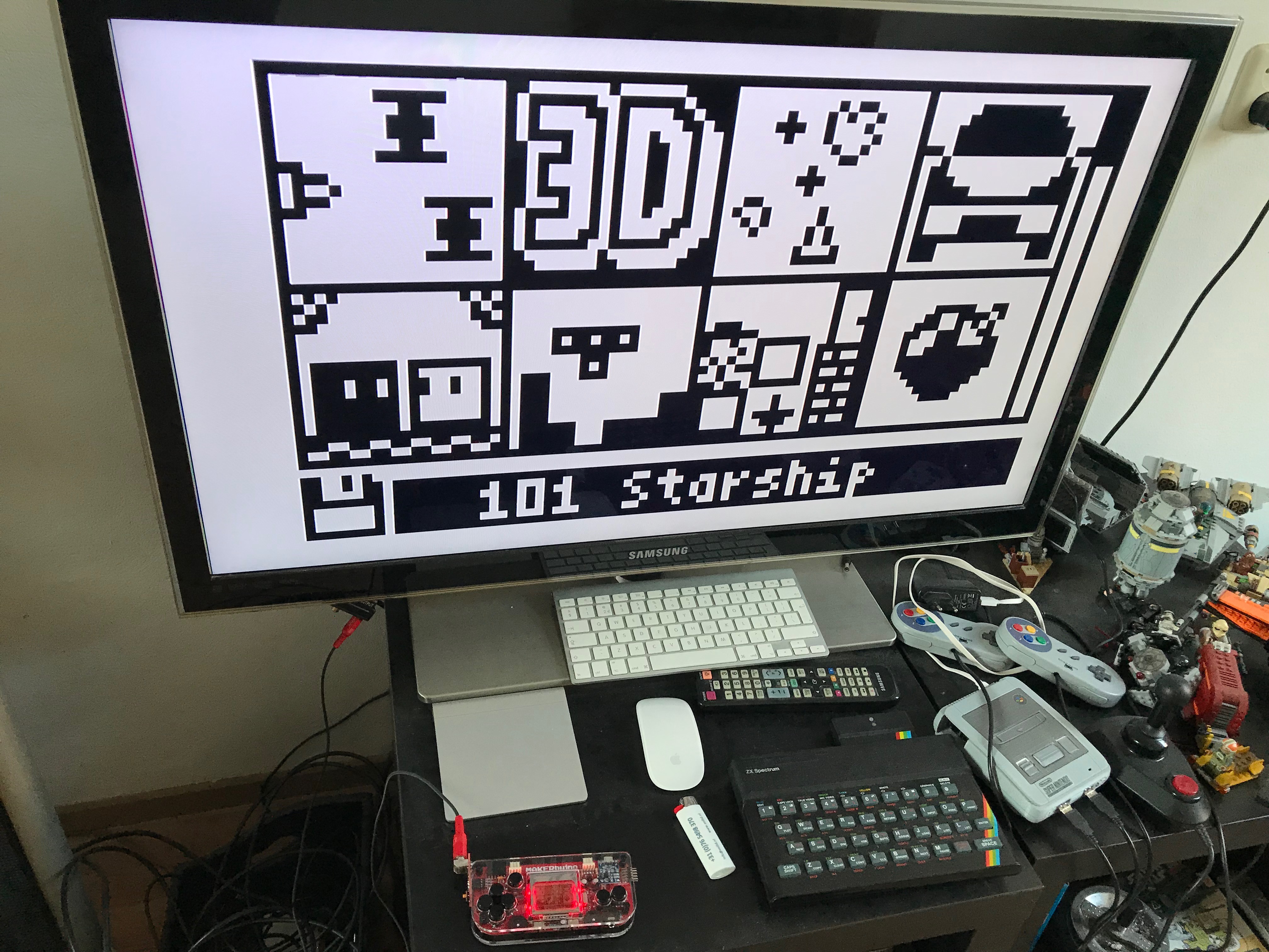
Hmm, most of the wires I used were very short. The longest component was the a/v cable, but even that wasn’t very long. It seems about the normal length for such a cable. I can post a picture of my setup soon in case there are any obvious mistakes I made.
Yesss! Got it working as well
Unfortunately it doesn’t work with jonnection’s video player as he’s accessing the SD card during playback. And the SD card uses the same MOSI and SCLK pins as the TV out Arduino. Maybe I can modify the code so the Arduino only receives data when LCD_CE is active low.
But it’s fun!
2 Likes
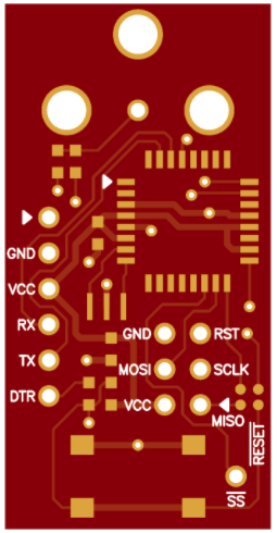
Designed a small TV out PCB that should plug in the side of the MAKERbuino. Just ordered a few of these. I added an option to monitor LCD_CS so data sent to the SD card (SCLK, MOSI) doesn’t get interpreted as screen data. Let’s hope it works…
2 Likes
This looks awesome. I’m eager to hear how good it works! 
@Ma_X, wowzie, amazing!
Which CAD software did you use for that?
The design looks very neat and clean. Please, keep us updated on this, I’m very very interested!
Hi @albertgajsak
I am using Altium Designer (and sometimes P-CAD). Boards should be here in a few days… I’ll keep you posted! I’m having a lot of fun with the MAKERbuino. Watch this space…
1 Like
Congratulations, Altium is a pretty advance software.
Sure thing, keep us updated. You’re doing some great progress!
By the way, where did you learn to draw PCBs?
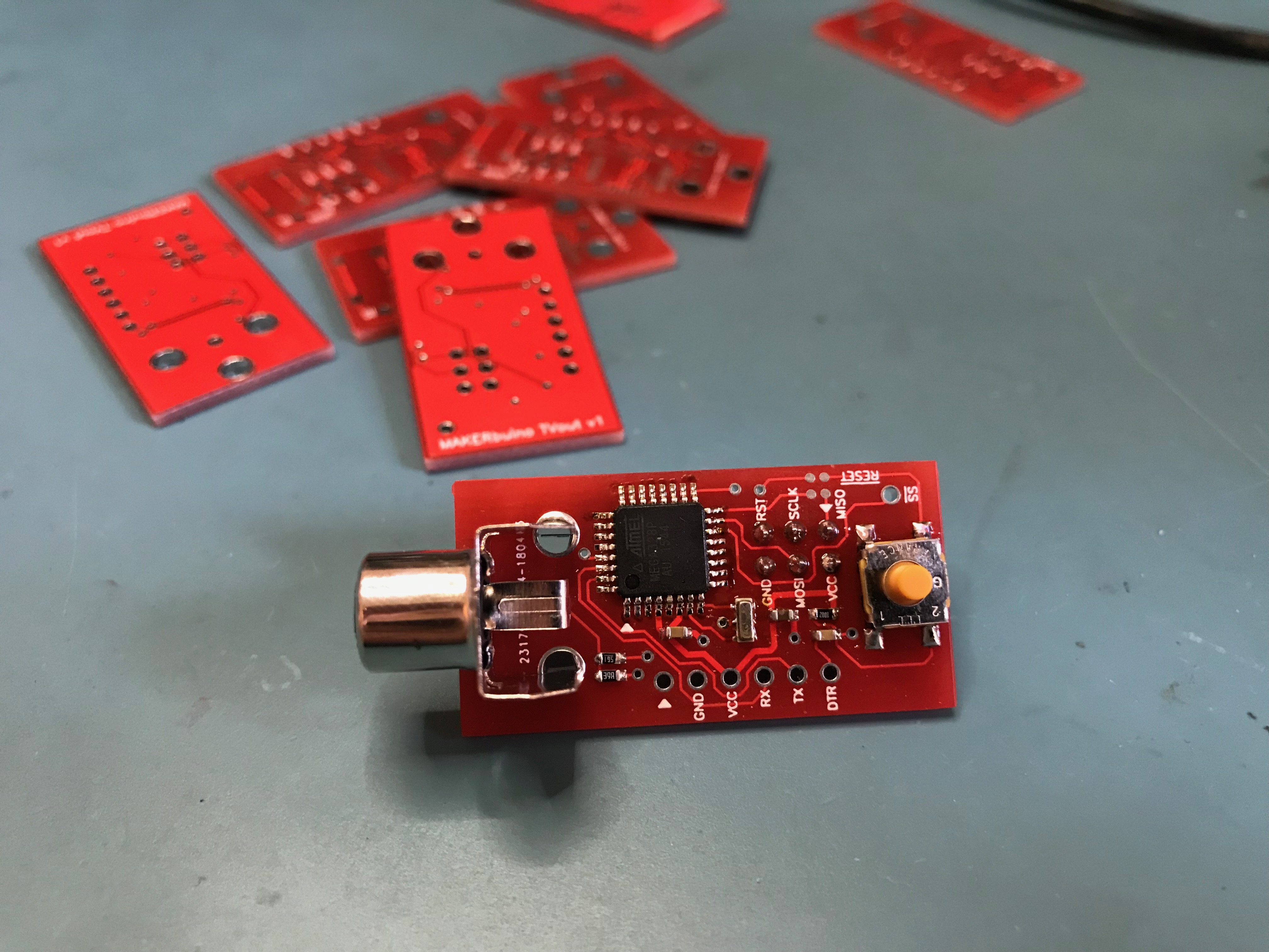
10 (red ) boards should arrive tomorrow! I know what I’ll be doing tomorrow evening.
I’ve been a design engineer all my life. Started with schematic capture and PCB design on MS-DOS, a long time ago, in a galaxy far, far away…
As a teaser, I am actually working on a MAKERbuino with integrated composite video. So basically combining both circuits on a single board. And I’ve replaced the 4 switches with a 4 directional miniature joystick. I’ll make a new thread when I am ready to order the boards.
1 Like
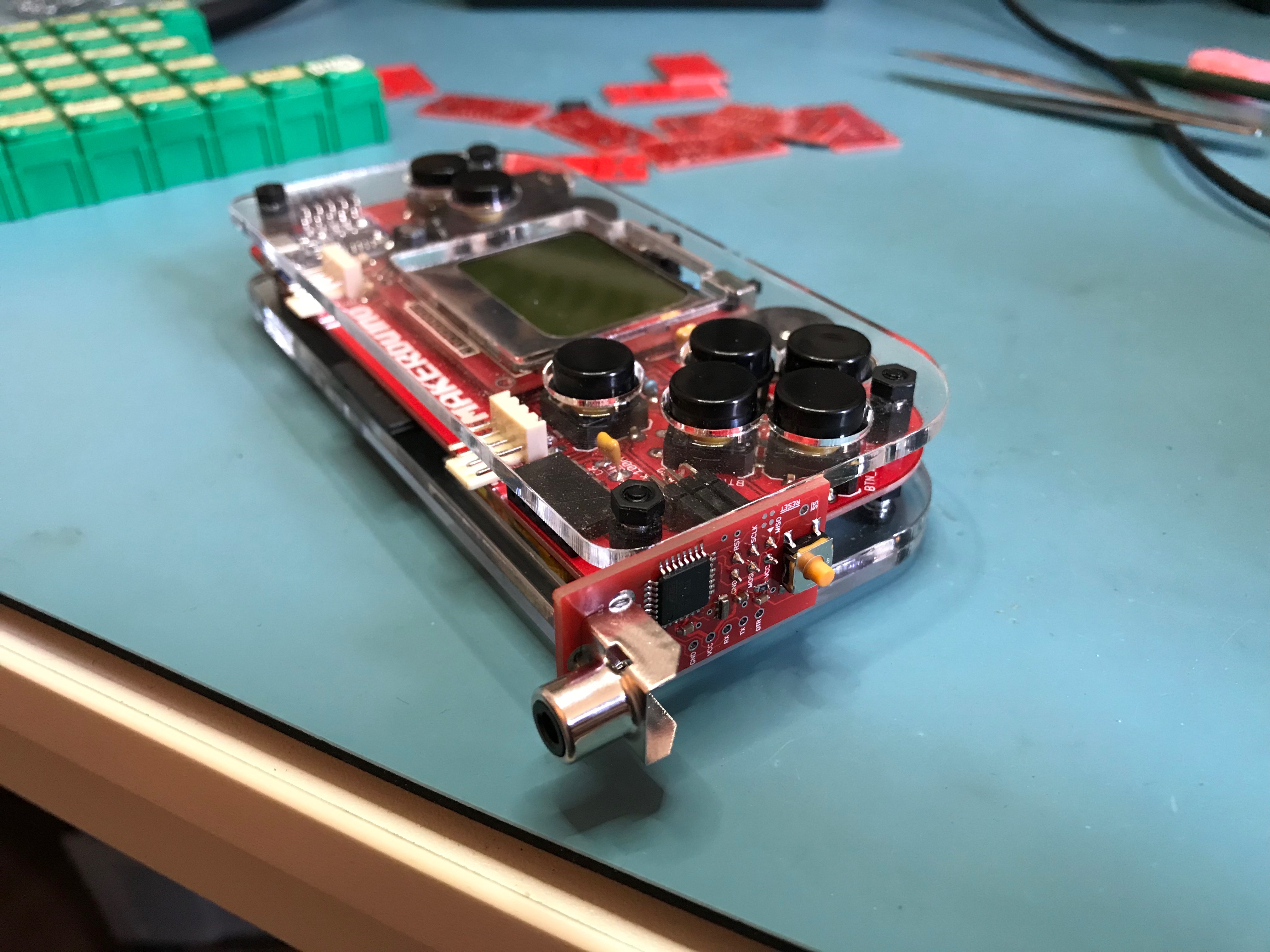
Got one assembled and it is working. Next thing is to see if I can use the #SS pin of the SPI bus to distinguish between data sent to the LCD and data sent to the SD card. These share the same pins that this board is also using. But so far so good!
2 Likes
I like it. A suggstion. You may have add 3 holes to fix a little pcb protection maybe, ad the card i near from whee you hand the console.
Thanks. Ah, you mean to prevent touching the board and accidentally pressing the reset button?
That could be done I guess. But then you would have to use wires to connect it to the ISP connector. Now it just plugs straight in. Or did I misunderstand your question?
No i like the position of your addon but yes, the idea could be to add a little pcb on top to avoid touching the card and press reset for example or making contacts or even just to make dirty on it.
Ah, I see! Yes, that would be a good idea. Maybe an acrylic cover like the MAKERbuino itself. I will probably make another minor revision anyway, so I will add some additional holes. Good feedback
Does the MAKERbuino have enough spare Memory, Processing Power, and I.O. to do the T.V. Output function with no additional external Hardware? (Other than the Resistors and RCA Composite Video cable). Just the extra bit of Code in it’s own ATmega chip, rather than the external Arduino.
My guess would be that this is impossible.
There is only one pin that’s free to use (D5). And the video signals must be generated following a very strict timing. If you take a look at the source code for the tv adapter you’ll see that almost everything is written in assembler. I think that the update-function of the Gamebuino library would compromise this code.
Furthermore the tv-out adapter code is using a lot of the available registers, so I think this would affect the Gamebuino library aswell.
1 Like
Is it possible to do it wirelessly