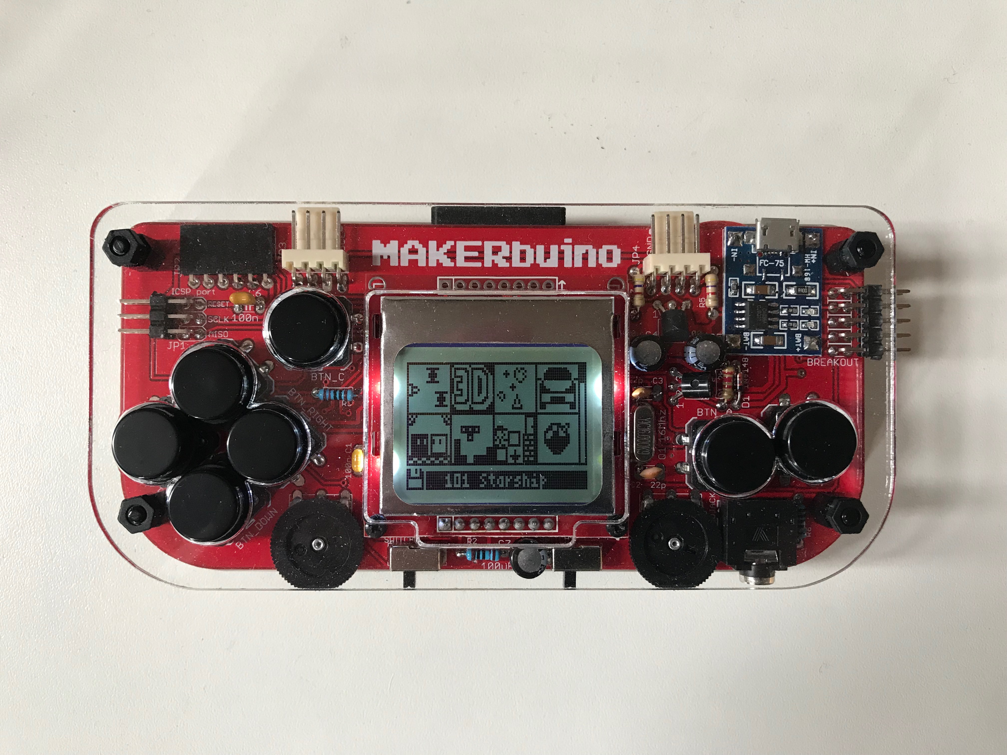
Finished building my MAKERbuino. And it works great! But unfortunately one of the four LEDs is not working. It is the one in the bottom right corner  LCD is still readable as you can see below. I can try to fix it by removing the LCD and then removing the metal bracket to see if it is just a bad solder joint.
I know it can be a bit tricky due to the zebra strip used under the metal frame, so I want to know if I can get a replacement LCD if I mess up…
I thought it would be worth it having a look first, before requesting a replacement LCD. Btw, I have a desoldering station, so it is not a big deal to remove the LCD.
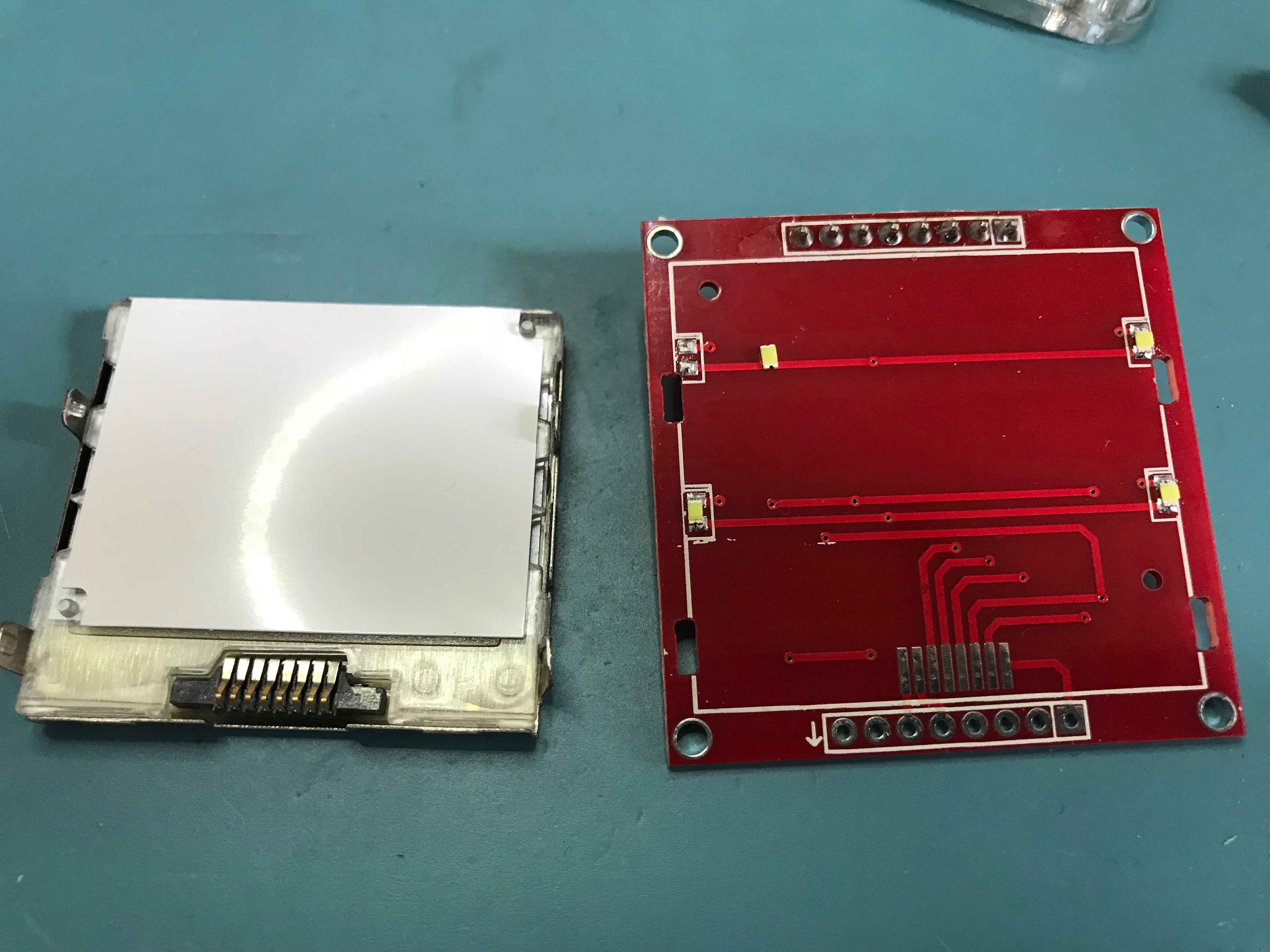
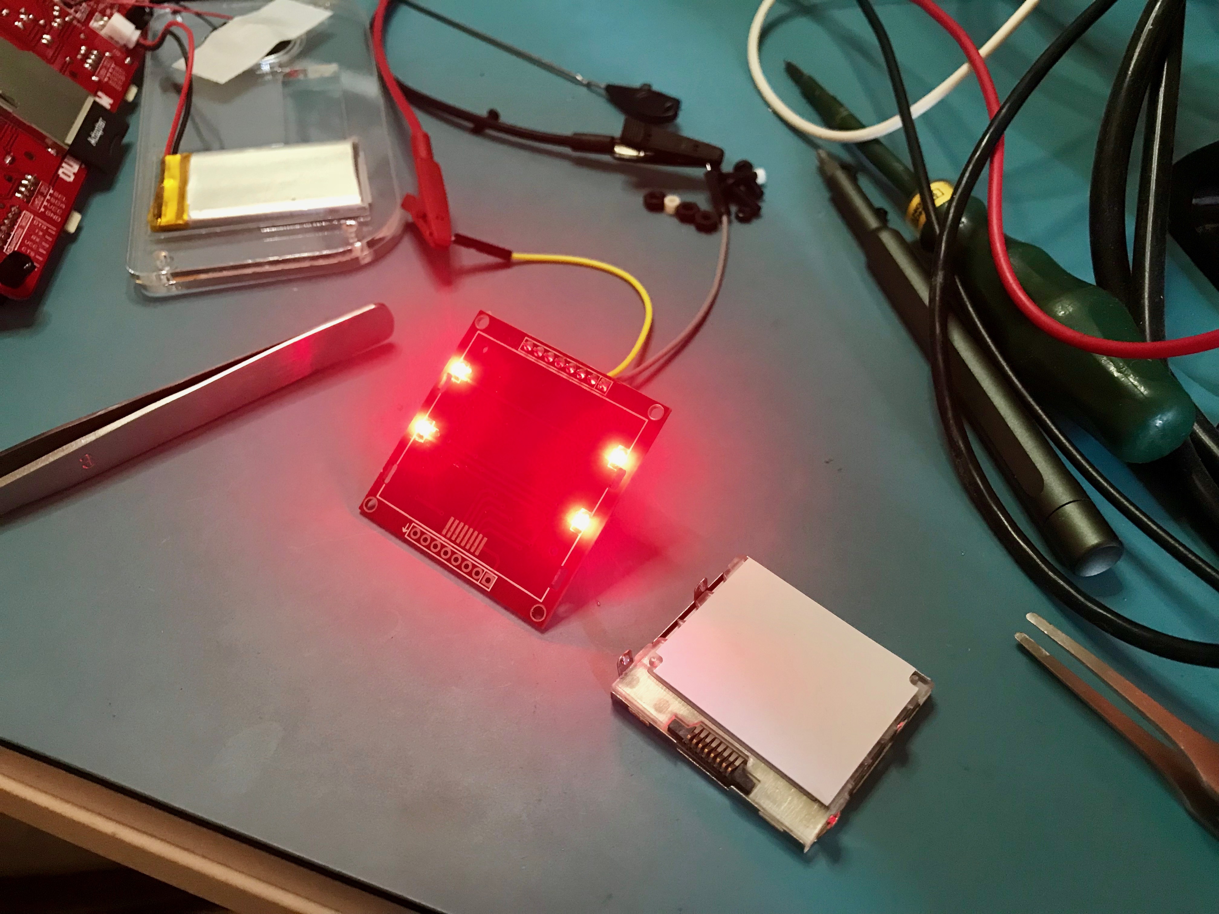
Found the problem. The LED fell out of the LCD module as soon as I removed the bracket. And by the looks of it, the metallic plating of the anode and cathode at the bottom of the LED is still stuck in the solder joints. Top and side plating is still on the LED, so I might be able to fix…
And surprisingly, there is no zebra strip between the LCD and the board, but an actual connector! Not too shabby 
*EDIT: While going through the schematic, I noticed that the LCD is powered by V_BAT directly, instead of VCC (3.3V). Looking at the datasheet of the PCD8544 (the LCD controller that drives the panel), the applied voltage is above the recommended supply of 3.3V. Was there a specific reason to do that?
Also the LCD_CE is pulled to V_BAT instead of VCC. Shouldn’t harm the ATMEGA328 because of the 10K pull-up. But it feels a bit weird to me… If someone can explain?
1 Like
@Ma_X, congratulations on a successful build!
I apologize for the screen defect… this is quite strange as we test every single screen before packing and shipping them to the customers.
Anyways, you’ve done a superb job fixing the issue and have just earned a few shiny badges
The LCD is wired directly to V_BAT in order to avoid noise generated by the microcontroller and everything else that is being supplied by the 3v3 regulator. This was causing problems on some older versions of the device so I just wired it directly to V_BAT.
@albertgajsak Things happen! I’ve got my tools, so no worries! Part of the fun of a kit. And it is working now. Managed to put the LED back in place. Working as a charm now I was even thinking of replacing the LEDs with red ones, to match the soldermask. But I have a second one, so I might modify that one 
Thanks for the badges!
1 Like
Oh boy, red backlight! Please do that and share some photos with us, I’d love to feature it in our new blog post.
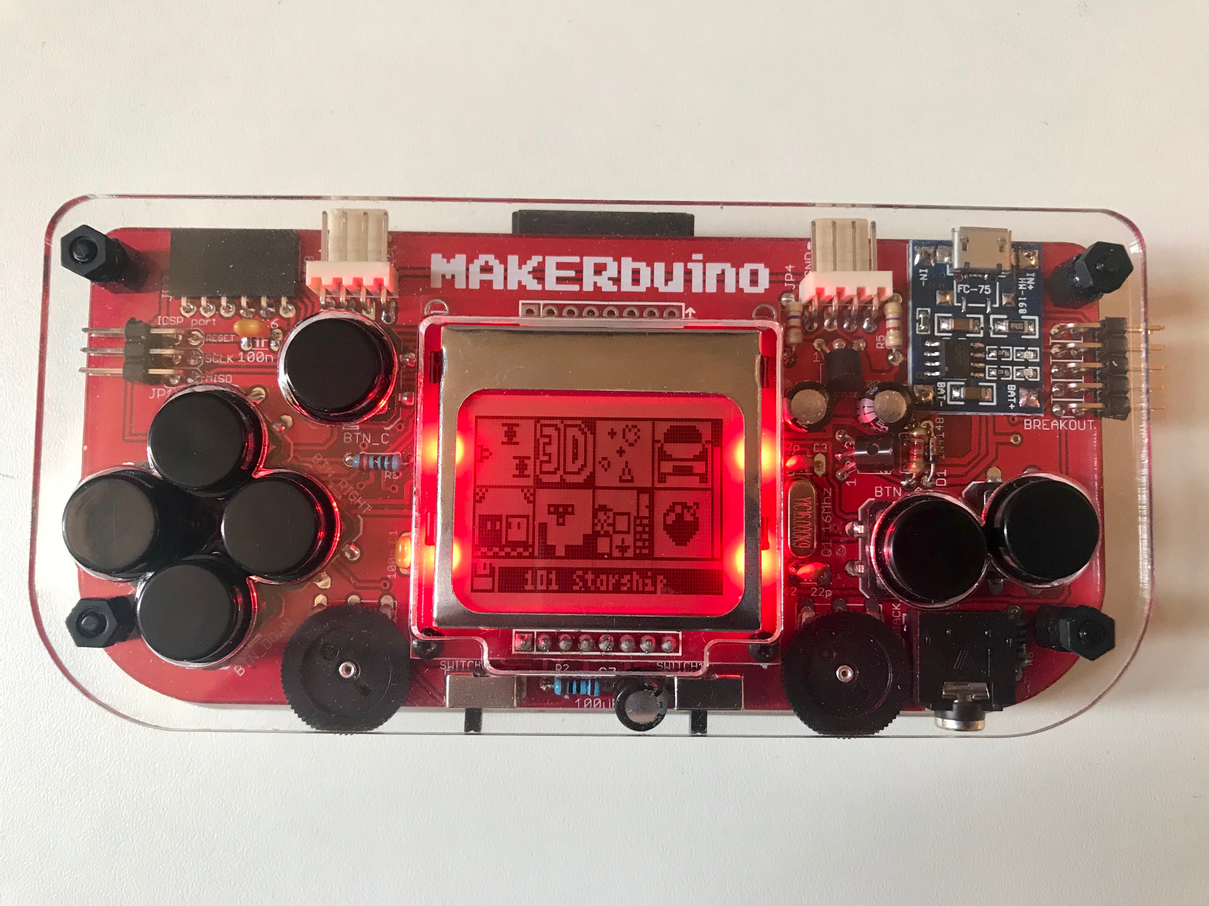
Done ! Replaced the white LEDs with red ones. I didn’t need to change the resistors. These are 150 ohms, which results in around 8mA per LED for the original white one ( 4.2V(Vbat) - 3V(LEDfv) / 150 )). The forward voltage of the RED led is around 2.1V, so each LED draws around 15mA. Total 60mA.
Shouldn’t impact the battery life that much. But it looks great! Feel free to feature it.
I might even change the charger board for a red one